Remember Heaven’s Gate? (not the Kris Kristofferson movie)
I am pretty sure that most intermediate malware developer’s/red-teamers know of Heaven’s Gate, an age-old technique that malware authors leverage to run 64-bit code from 32-bit processes using Wow64, which emulates a 32-bit system on 64-bit machines (if you are not familiar with it, I HIGHLY recommend reading on it first). The system creates a 64-bit process and creates a 32-bit environment, inside which the 32-bit program runs.
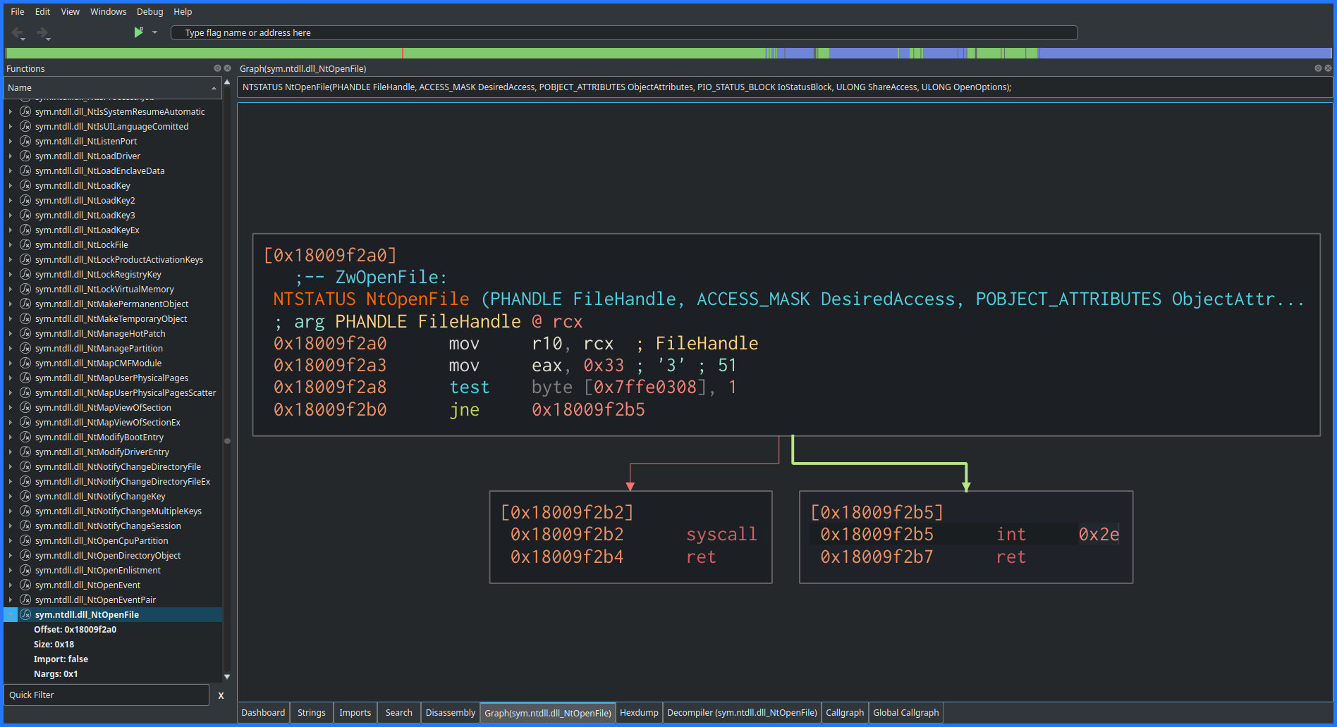
For example, note the implementation of NtOpenFile on x64 systems. Notice how the function makes a syscall?

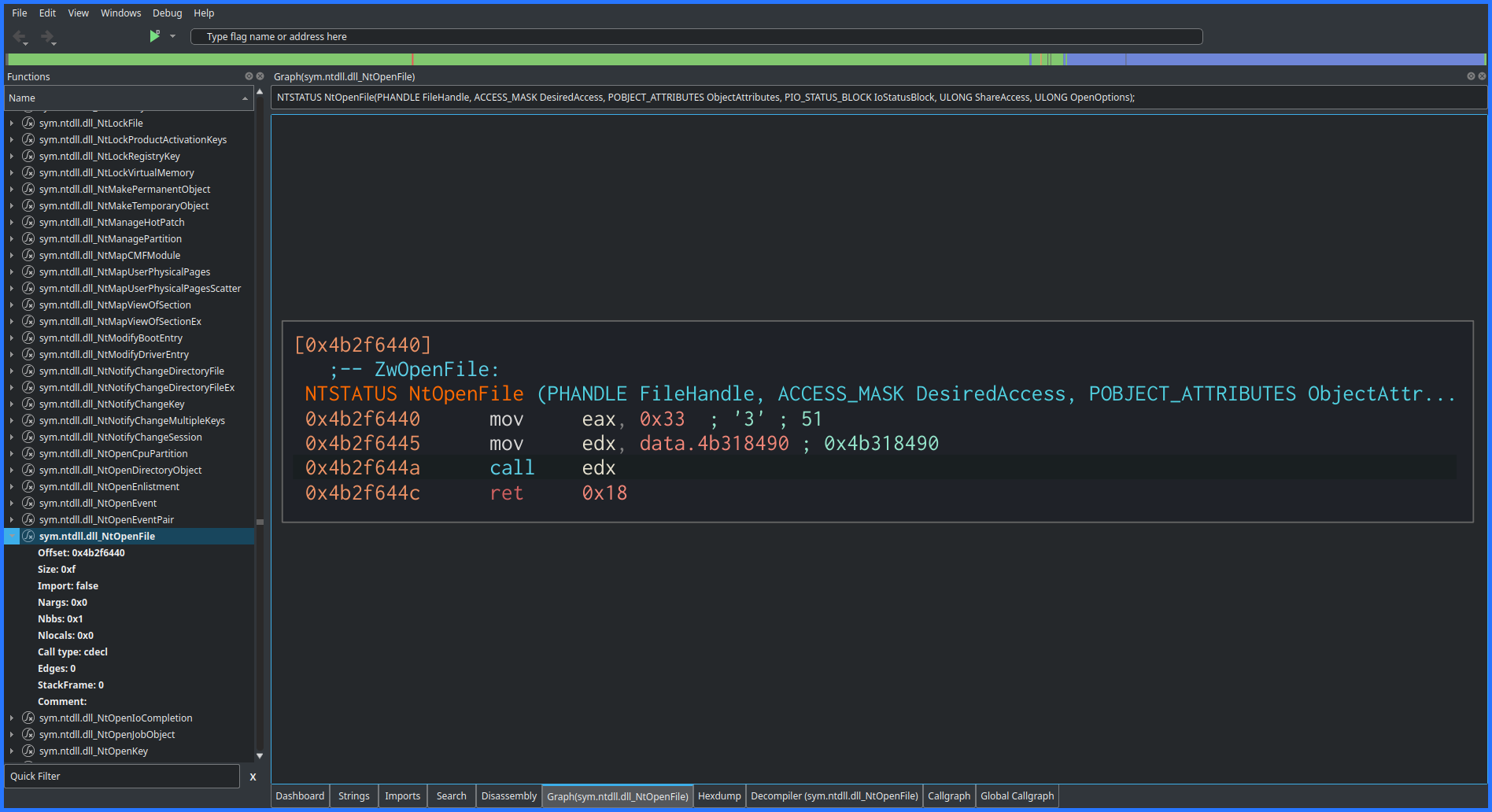
Meanwhile, looking at the 32-bit implementation of the same, notice how there are no syscall instructions? Rather, it is calling some other function (also see that 0x33? In a way, this blog is all about that!)

Now, Heaven’s Gate technique did receive a solid punch-in-the-gut when Windows 10 introduced Control-Flow-Guard(CFG) but hackers came back stronger (see Sheng-Hao Ma’s HITB Talk)
However, the main thing I want to talk about in this blog is how the segmentation register comes into all of this with the whole “0x33-for-64-0x23-for-32 stuff” (if you have read through Heaven’s Gate, you know what I am talking about). Initially, I found it very confusing, so, this is my attempt to break the thing down for my fellow security researchers struggling with the same!
(A much-needed) Glossary of Terms
Before we proceed, we need to define certain terms which will keep reappearing throughout the blog. The below table, taken from OSDev Wiki and some other related terms:
| Term | What the 🦆 it means |
|---|---|
| Segment | A logically contiguous chunk of memory with consistent properties (from the CPU’s perspective) |
| Segment Register | A register of your CPU that refers to a segment for a particular purpose (CS, DS, SS, ES) or for general use (FS, GS) |
| Code Segment (CS) | This segment is used for storing executable code. When the CPU executes an instruction, it reads the code from the memory pointed to by the CS segment register. |
| Data Segment (DS) | This segment is used for storing data that is accessed by the program. For example, variables and arrays are typically stored in the DS segment. |
| Stack Segment (SS) | This segment is used for storing the program stack, which is used to manage function calls and local variables. The stack grows downwards from the end of the segment. |
| Extra Segment (ES) | This segment is an additional data segment that can be used by the program. |
| FS/GS Segments | This segment is an additional data segment that was originally intended to provide thread-local storage. |
| Segment Selector | A Segment Selector is a 16-bit binary data structure specific to the IA-32 and x86-64 architectures. It is used in Protected Mode and Long Mode. Its value identifies a segment in either the GDT or an LDT. It contains three fields and is used in a variety of situations to interact with Segmentation. |
| Segment Descriptor | An entry in a descriptor table. These are a binary data structure that tells the CPU the attributes of a given segment. |
| Global Descriptor Table (GDT) | The GDT is a data structure that is used by Intel x86-family for defining the characteristics of the various segments like the size, the base address, and access privileges like write and executable. |
| GDTR | The GDT is pointed to by the value in the GDTR register. This is loaded using the LGDT assembly instruction, whose argument is a pointer to a GDT Descriptor structure |
Phew! Those are a lot of definitions

Side Note: If all of this sounds complicated and too much to unpack, I would suggest just try to understand what segments and segment selectors are, and we should be good for a while!
What is the deal with 0x23/0x33 Segment Selectors anyway?
Remember the little 0x33 we spotted earlier in the 32-bit implementation of NtOpenFile in ntdll.dll? It essentially allows us to switch modes into 64-bit mode.
But how does the whole thing work behind the hood? Where does this whole "0x33 for 64-bit and 0x23 for 32-bit" narrative come from?
To answer that, we need to look into the GDT a bit. Wikipedia introduces GDT as:
The GDT is a table of 8-byte entries. Each entry may refer to a segment descriptor, Task State Segment(TSS), Local Descriptor Table (LDT), or call gate.
The same article also mentions the following:
In order to reference a segment, a program must use its index inside the GDT or the LDT. Such an index is called a segment selector (or selector). The selector must be loaded into a segment register to be used.
The part we would be focusing on is the segment descriptor part of the definition.
Segment Descriptors
The x86 and x86-64 segment descriptor has the following form (source):

The important parts we need to consider here are:
- Limit: 1. The segment limit which specifies the segment size
- G=Granularity: If clear, the limit is in units of bytes, with a maximum of 2^20 bytes. If set, the limit is in units of 4096-byte pages, for a maximum of 2^32 bytes.
- D/B:
- D = Default operand size: If clear, this is a 16-bit code segment; if set, this is a 32-bit segment.
- B = Big: If set, the maximum offset size for a data segment is increased to 32-bit 0xffffffff. Otherwise, it’s the 16-bit max 0x0000ffff. Essentially the same meaning as “D”.
- L=Long: If set, this is a 64-bit segment (and D must be zero), and code in this segment uses the 64-bit instruction encoding. “L” cannot be set at the same time as “D” aka “B”. (Bit 21 in the image)
- AVL=Available: For software use, not used by hardware (Bit 20 in the image with the label A)
- P=Present: If clear, a “segment not present” exception is generated on any reference to this segment
- DPL=Descriptor privilege level: Privilege level (ring) required to access this descriptor
From this, we can presume the values of some fields for the time when we are in 64-bit land:
- The Long bit flag must be set to 1 while the D/B bit must be unset.
- The Granularity flag must be set for 32-bit (because it can only address a limited amount of memory) and unset for 64-bit memory
- The Limit must be 0 for 64-bit (because it can address 2^64 bytes, aka 16 Exabytes of memory) while it must be set to 0xFFFFFFF for 32-bit (because it can address only 2^32, aka 4 GB of memory)
Getting things real for a moment
In real mode, only 16-bit register values are used, yet a CPU can address up to 1 MB of physical memory, how? When in real mode, memory is divided into segments, and each segment is 64 KB in size. The CPU generates a physical address by combining a 16-bit segment value with a 16-bit offset value, i.e, the segment register is multiplied by 16 (shifted left by 4 bits) and then added to the address to give a 20-bit address and allowing the whole 1 MB of memory to be accessed.
However, whenever the system kicks into Protected Mode, the segment register starts behaving differently. It acts like a selector which is split up into the following parts:

-
Descriptor Index and Table Index (TI) :
-
The 13 bit descriptor index selects one of up to 8K descriptors in either the GDT and LDT, as specified by the TI bit.
-
Therefore, these 14 bits allows access to 16K 8-byte descriptors.
-
-
RPL :
- The desired privilege level of the program.
- Access is granted if the RPL value is lower (higher in privilege) than the AR of the segment. Otherwise, a privilege violation is issued.
So when we see something code like:
call 0x33:address
or
call 0x23:address
It means that the selector bits are changing. Looking at the Linux kernel source (to the people who thought this was just related to Windows: pat-pat kiddo, you might want to start over again), we see that the default selector value for 32-bit is 4 and for 64-bit it is 6.
Therefore,
- For 32-bit the register value becomes:
0000000000100(4 for the selector value) +0(because we are using the GDT) +11(which means we are in ring 3) =0000000000100011= 35 = 0x23 - For 64-bit the register value becomes:
0000000000110(6 for the selector value) +0(because we are using the GDT) +11(which means we are in ring 3) =0000000000110011= 51 = 0x33
So now we know where those 0x23 and 0x33 come from, but then again, why did we have to choose the selector values of 4 for 32-bit and 6 for 64-bit?
Well, the GDT has 2^13 = 8192 entries corresponding to the 13-bit selector. Out of which, entries 4 and 6 correspond to the following values:
Entry 4

Entry 6

Remember when we talked about Segment Descriptors, we theorized the values for the Flags and the Limits for 32-bit mode and 64-bit mode?
-
Note how the Limit value is 0 for 64-bit and 0xFFFFFFFF for 32-bit, as expected?
-
Looking at the flags, the
fbpart stands for the access bytes but the c for 32-bit and 2 for 64-bit can be imagined as:
-
Therefore,
- For 32 bit we see the Granularity and D/B flags set, as expected.
- For 64-bit, we see the Long flag set as we had previously theorized
Therefore, we can now see that the 4 and the 6 correspond to these respective entries in the GDT for 32-bit and 64-bit respectively. Therefore, even if the segment descriptor points to the same address, the selector determines in which mode the CPU executes it. As Marcus Hutchins puts it:
So there you have it, both segment descriptors point to exactly the same address, the only difference is then when the 0x33 (64-bit) selector is set, the CPU will execute code in 64-bit mode. The selector is not magic and doesn’t tell windows how to interpret the code, it’s actually makes use of a CPU feature that allows the CPU to easily be switched between x86 and x64 mode using the GDT.
Closing Words
This blog was focused on a very small part of a well-known technique used by malware authors. The main motivation behind this was to understand the low-level mechanisms which make these techniques possible, and to have more in-depth knowledge about the magic which happens under the hood. Till next time, Happy Hacking!

References
- Rebuild The Heaven’s Gate: from 32-bit Hell back to 64-bit Wonderland - Sheng-Hao Ma
- Segment descriptor
- Protected Mode Memory Addressing
- A coin miner with a “Heaven’s Gate”
- The 0x33 Segment Selector (Heavens Gate)