Why does `add rax, rbx` encode to `48 01 D8` on x86_64?
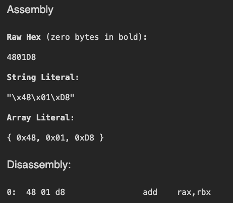
While learning more about x86_64, I went down a rabbit hole recently, and it all started with this:
For the first time, I stopped and asked myself - “Where are these values are coming from?”. This blog is an attempt to answer these questions for myself. A thing to note that is for the sake of simplicity and my own mental sanity, I will focus on JUST THIS ONE ASSEMBLY; x86_64 assembly has a lot of moving parts which change with instructions, value types and more - covering it all on a blog would be very difficult. So, we stick to just this one instruction and break down all the relevant concepts.
The Bible of x86_64
For this guide, we would refer to Intel® 64 and IA-32 Architectures Software Developer’s Manual (Combined Volumes: 1, 2A, 2B, 2C, 2D, 3A, 3B, 3C, 3D, and 4) which I will refer to as THE BOOK throughout this guide.
The Three Bytes
48          01          D8
REX prefix  Opcode      ModR/M byte
There are three bytes we need to consider. Starting with the first one:
The REX Prefix: 0x48
First things first: WTH is a REX prefix?
Searching for the phrase “REX Prefix” in the book gives us 248 results. Here are some snippets which helped me understand what it does:
[3-2 Vol. 1] REX prefixes allow a 64-bit operand to be specified when operating in 64-bit mode. By using this mechanism, many existing instructions have been promoted to allow the use of 64-bit registers and 64-bit addresses.
[Vol. 1 3-19] REX prefixes consist of 4-bit fields that form 16 different values. The W-bit field in the REX prefixes is referred to as REX.W. If the REX.W field is properly set, the prefix specifies an operand size override to 64 bits.
Before going further, lets see how 0x48 looks as a Base2 number:
1 | |
We will divide this in two parts: 0100 and 1000
The first 0100 is fixed and identifies this byte as a REX prefix. Why 0100? Mostly due to historical recycling choices.
This leaves out the 1000 part. From Vol. 1 3-19 we can see that they are a part of the 4 bit field in the following order:
1 | |
So what are REX.W, REX.R, REX.X and REX.B?
REX.W(Width): Changes the operand size from the legacy 32-bits to 64-bits. This is the only bit that alters execution size rather than just targeting a register. Since we are looking at 64 bit code - this is set to1(See: Vol. 1 3-19)REX.R(Register): Extends themodR/Mreg field. It allows the instruction to access the higher 8 General Purpose Registers (GPRs)R8–R15, as well as extended XMM/YMM registers - we dont need any of this complex stuff for this particular case as we just working withraxandrbx- so it is set to0.REX.X(Index): Extends theSIBindex field. It is used specifically in complex memory addressing modes to utilize the extended GPRs as the scale/index register. Again, we dont use any of these complex fields, so it is set to0.REX.B(Base): Extends themodR/M r/mfield or theSIBbase field. Similar toREX.R, this allows the source/destination operands to be mapped to theR8–R15registers, and therefore, for our case, it is0.
So, this is why we get the 1000 value. So together with 0100, we get 01001000 - the 0x48 byte we see. That’s one mystery solved.
Now, instead of going the next Opcode byte, we would take a look at the third piece of the puzzle: the Mod R/M byte. This would help us better understand the Opcode byte later.
The Mod R/M byte: D8
The book describes the Mod R/M byte as follows:
1 | |
There is also something called an SIB byte, but we wont need that for our chosen example. Again, let’s convert the value to Base 2:
1 | |
Now, if we take a look at Figure 2-1 from the book:
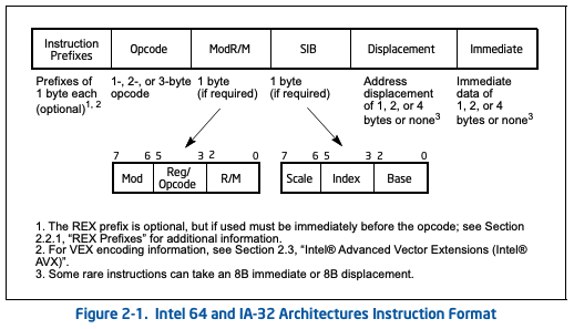
Focus on the Mod R/M byte expansion. So, if were to dividie the bits as shown, we would get:
1 | |
The Mod bits
The Mod bits tell the system about the nature of the operands - aka if you are adding to a register, address, offset, etc. It can take one of the 4 values:
| MOD | Example | Description |
|---|---|---|
| 00 | add [rax], rbx |
Memory Address Mode (No Displacement) - the operand represents a memory location using the register as the base address |
| 01 | add [rax+0x10], rbx |
Memory Address + 8-bit Displacement - Points to memory with an 8-bit signed value added to the base register |
| 10 | add [rax+0x10000] |
Memory Address + 32-bit Displacement. Points to memory with a 32-bit signed value added to the base register |
| 11 | add rax, rbx |
Register Direct Mode - the operands are both registers - which is the case for us |
Therefore, we understand why the bits for Mod are 11.
The Reg and R/M bits
These are 3 bit values which act as selectors. Essentially, it tells the system which registers we are dealing with at the moment (we will talk about directionality later when we see the opcode part). Usually, they are combined with the REX prefix (REX.B extends R/M, and REX.R extends Reg) to act as a 4 bit selector - with 16 options.
In our case, since both of them are zero, we can condense the values to:
1 | |
So for our case,
Regis011akarbxR/Mis000akarax
So with everything combined - we get 11 011 000 aka 0xD8 - the third byte has been demystified! Finally the last piece - the OPCODE byte!
Opcode Byte: 0x01
So at this point we know how the system:
- figures out if its a x64 instruction or an x86 instruction
- What registers to use
- If we are referencing registers or addresses
But two questions remain unanswered:
- What is the operation? Are we adding stuff? Are we subtracting stuff? What’s going on?
- What is the direction of the operation? When we add
raxandrbx, which registers gets the final value?
All this information is contained in the opcode byte. Again, converting the value to Base 2:
1 | |
Breaking it down:
1 | |
Going part by part:
Bits 7:6 (⁶🤷♂️⁷) - It denotes the region of the Opcode table we should be looking at. Since for our example we are performing an arthimatic operation, we need to look at the ALU region of the opcode map.
Bits: 5:3 - These are the selector bits - responsible for checking which of the 8 classic operations to perform:
Bits 5:3 Operation 000 ADD 001 OR 010 ADC 011 SBB 100 AND 101 SUB 110 XOR 111 CMP Since we are using the
ADDoperation - the value for us would be000Bit 2 - This indicates the CPU if it should expect a
Mod R/Mbyte next:- Bit 2 = 0: CPU expects a ModR/M byte next, reads Reg and R/M fields to find both operands
- Bit 2 = 1: CPU skips ModR/M entirely, hardcodes RAX as the destination, reads the remaining bytes as an immediate value
Bit 1 - This bit controls the direction of the operation and answers the question, “why is the final result stored in rax and not rbx?”. Setting it to
0indicates that theR/Mfield is the destination which we saw is set torax. If it was set to1, the destination would have beenrbx.Bit 0: This just tells the CPU about the size of the operand. If the operands are 8bits (for example, if our expression was
add al, bl) it is set to0, else1
So now we can read 0x01 as: “Hey, look at the ALU region of the opcode map - and perform the ADD operation. Store the result in whatever R/M says and btw, both operators have sizes greater than or equal to WORD“.
So at this point we can see why add rax, rbx results in 48 01 D8. While we did not touch a lot of topics (like SIB for one) - this is still good stuff to get us started. Before I leave, I would like to throw a little challenge to the readers who made it this far:
Why do both
48 01 D8and48 03 C3encodeadd rax, rbx? Why does the assembler pick the first one?
Hint: Look how Opcode byte flips affect the Mod R/M. If you get stuck, reach out to me @whokilleddb. Till then, Sayonara, Nerds!